What follows is a somewhat technical description of what it was like to build the Triple Helix. I worked on the design intermittently for nearly eight years, and the fabrication on and off for two years, and so the story is not exactly linear. But, then again, in the business of making waves, linearity is often overrated. It has been pointed out to me more than once that most people do not share my infatuation with exact quantities of pulleys, and could care less whether or not a bearing has an inner diameter (ID) of 2-3/8 inches. I am envious of those people who have managed to retain a larger view of the world and not get lost in such details. But to those folks like myself who frolic in such minusculia, please read on!
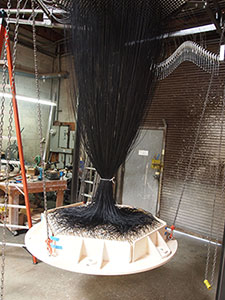
Attempting to use mechanical means to add three waves at 120 degrees proved an incredibly fertile problem, generating all sorts of ideas, but never revealing a satisfactory solution. The Triple Helix, as it ended up, has several distinct elements which all work together. The lower wavescape is made of 1,027 blocks of wood supported by an equal number of black strings. The strings pass through a matrix which houses an array of 9,280 pulleys designed to add together the movement of three plane waves. The waves are generated by three rotating aluminum helices. The whole thing is held together by a welded steel frame and supported by three legs. That’s it!
Prototype
Over the years I’ve come up with all sorts of ways of adding three waves together, but for one reason or another, none of them took root. A breakthrough finally came about due to a dumpster find. About five years ago, I discovered sixty sheets of tinted polycarbonate that had been removed from decommissioned computer server cabinets and thrown out. I hauled them into my shop and stood them against a wall where they gathered dust. In 2011 I cut one up, to prototype an idea I had for adding non-orthogonal waves.
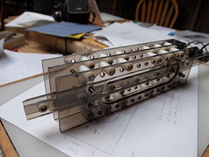 The prototype was made of two parts: a stationary triple-tiered matrix and matching strips of pulleys that slid in and out. One end of each string was attached to a lower wooden block, and the other end tied to the top of the matrix. As the string passed through the matrix it turned to loop around each of the three sliders, and in this way imparted motion from the three helices to the wavescape. The prototype worked great, and the fact that I had a limited number of polycarbonate sheets provided a crucial constraint, giving me good reason to go with a specific size for the sculpture. (One problem with making a sculpture for kicks, rather than for commission is that there are not enough constraints. Things such as determining a scale prove annoyingly difficult).
Matrix
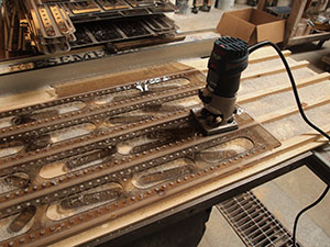 I drew up the matrix, maxing out the polycarbonate, and had it CNC routed into strips and drilled with over 20,000 holes. When I got them back, they required a couple weeks of additional work with a table saw, band saw, and router to wrestle the strips into shape.
Next I spent a couple weeks assembling the matrix with steel dowel pins and nylon rollers. The crux of the system was that there had to be just the right amount of gap to insure proper alignment between the hexagonal tiers. In addition, this gap had to be big enough to allow the roller to turn freely and function as a pulley, but be small enough that there was no way the string could get jammed in it. Unfortunately, my strategy for gapping the rollers was flawed. I was planning to pound all the pins tight, and then jam in a long custom shim to spread the slats out the right amount. But when I did, the expansion along one face caused everything to warp. To my horror, what had been flat and very precise turned into a bowl on the verge of popping apart. With some measure of desperation, I flipped the tier upside down and began spreading the other side to straighten it. It turned into a miserable week of work where I custom gapped each of the 10,000 dowel pins, while keeping an eye on the flatness, and keeping the overall growth within tight tolerances.

Helices
After the matrix was together I had to figure out what sort of wave generating mechanism to use. Camshafts, helices and rings all produce wave motion, but each has its own particular flavor of disadvantage. Typically, I would have this major element sorted out before getting so far along, but in this case I just couldn’t see the entire sculpture in my head. Since it was not a commissioned piece, I took the riskier approach of investing a lot into one part, with the hope that I would figure out the rest later.
To understand why I finally went with helices, I have to take you back to 1988 when I was building a redwood strip canoe in my parent’s backyard. I was almost done, and went to put a layer of fiberglass on the outside, when, somehow, the epoxy didn’t set. Rather then drying, it just stayed tacky and so I couldn’t sand it. I had to quit working on it. I still have the canoe. To date it remains my longest unfinished project. About that time a friend of the family, Gary Scott, offered me a job as part of his crew building magnetically shielded laboratories. I ended up working with these guys on and off for years, and besides learning how to complete complex projects, I also became great friends with the crew, and in 2002 one of them, Bruce Douglas, let me share his garage workshop in Oakland. At that point I was in my third year trying to make mechanical caterpillars, and Bruce introduced me to a local machinist Frank Bletsch, who has generously mentored all sorts of newbie metal workers, and who, besides giving me lots of fabrication tips, handed me a catalog from a surplus supply house, C&H Sales.
By 2006 I had moved into my own shop and had just finished the Square Wave. The Square Wave added together two waves at right angles. I began work on the next obvious step: adding three waves at 120 degrees. One hare-brained idea I had required a lot of large bore bearings. On page 32 of the C&H catalogue I found a 2-3/8 ID bearing for five bucks. I bought one. It was the smoothest thing I had ever felt. Since I had just finished a magnetically shielded laboratory, I had some extra cash, and so I bought all 125 bearings they had. Next, using a handmade cold saw that Frank lent me, I cut a big chunk of aluminum and put it in my lathe. Partly because my lathe is from 1916, and partly because I tried to plunge a large diameter mill cutter straight into the end of an aluminum rod, the whole project quickly became untenable. Deciding to cut my losses, I put the bearings in a box, and spent the next 9 months making the Double Raindrop instead.
By 2012 I had finished the Triple Helix matrix and was considering what wave generating mechanism to use, when I suddenly remembered those bearings. What if I made a helix by bolting together offset disks? Could I use those bearings as slider attachments? The matrix had three tiers of 37 rows and so I would need 111 bearings. I found the box and counted them – there were 110! Almost perfect! I remembered using twelve of them for the pedals on the Parkcycle, but that should still leave 113. I called up everyone I might have given one to, as well as C&H and every bearing supply house I could find online, and yet they were impossible to match. Then I remembered the prototype I had made six years earlier and dug it up and sure enough there were two bearings I could cannibalize. So I even had an extra! Like the polycarbonate, the material on hand constrained the problem enough to come up with a solution.
I sketched up the helix design based on the bearings. The mechanical engineer Michael Prados agreed to take a look at it and was able to model the helix and cycle it under the expected loads. He determined that it could be made from 7075 aluminum. I had these disks CNC lathed and the bearings slid right on.
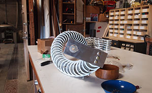 For the white collars on the outside of the bearings I invested in a horizontal band saw so I could slice up an aluminum tube. I turned each ring on my lathe. I had to turn them twice, because the first time I squeezed them too hard in the chuck and so the machined bore wasn’t actually round. After tapping the collars to receive the eyebolts, I could then assemble the helices. I had to do this twice as well. The first time I relied on the accuracy of the machining to index each element. This didn’t work. And so I took them apart and redid them in a fixture to get the curvature right.
Frame
 With the Matrix and Helices completed, I turned my attention to the steel frame that held everything in place. Once I realized the advantages of suspending the frame from a truss that spanned adjacent helix arms, this part of the sculpture only took a month or so to design and build. A couple waves ago I switched from flux core to MIG welding and that made things a lot cleaner. The horizontal band saw proved fantastic for cutting up steel.
 Legs
Legs
As the combined weight edged past a thousand pounds, I became concerned. The pick points were close enough together that the square foot load on my ceiling would be too great and so I couldn’t hang the sculpture in my shop. I decided to make three legs and bolt them to the floor. On the top of each leg I mounted a chain hoist so I could raise the frame and work on it at different heights. Having the sculpture free-standing makes for a certain poetry, but the legs are not necessary if its final home has a more robust ceiling structure.
Strings
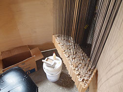
One of the main advantages of this design is that all the strings are the same length. And so it only took a day to use a hot knife and cut up three thousand yards of black Dacron to the right length. Putting the strings in was straightforward, but definitely a two person job. With all the sliders binder clipped in place, I stood on a ladder and threaded a 10 inch needle through the matrix. Someone below hooked a string on, and I pulled it up and tied it to the top tier. Nevertheless it took a few days because there are 1,027 strings. Richard Vertz, the ceramicist with whom I share the warehouse with helped, as did my friend Dan Torop who was in town.
Blocks
One of the first things I had done on this sculpture was to experimentally determine the weight of each block. The minimum weight needed was 40 grams per block. (I prefer Imperial units for everything except for weights under a pound, where I am more comfortable with grams. This is because Richard has a triple beam gram scale I’ve been borrowing for the last ten years.) If the block weighed anything less than 40 grams, it just wouldn’t pull the string through the pulleys. Since the force due to friction in the upper tier, after the string had gone around nine pulleys, was ten times the weight, there was penalty to making the block any heavier than need be.
Each helix imparts a sine wave. A bit of trig reveals that all three waves added up would result in a maximum travel of 3.4 inches between two adjacent blocks. A five inch length would ensure that a block wouldn’t escape from the wave even if things got out of whack. I considered using dowels, but preferred making the wave out of close packed hexagons, and so I decided to mill the blocks out of lumber. After playing around with densities of various woods, basswood became a clear choice. Besides being lightweight, it is also easy to work with, dimensionally stable and also doesn’t have a lot of character. When I’m trying to make a movement with over a thousand elements, I’d prefer that each individual element is fairly bland.
 I rode my rickshaw to the local lumberyard and bought a bunch of 8/4 Basswood. When I got it back to the shop, it looked like such a big pile that I wondered if I miscalculated how much I needed and was off by a factor of ten. I had thought it would only take a couple days to make the blocks, but the cutting, planning, sanding and finishing (two coats polyurethane) took two weeks. Cutting them to length on the chop saw left hairy edges that needed to be sanded off by hand. Each end had six sides, and so that’s twelve per piece. Times 1,027 equals 12,324 sides. Times one second per side equals four hours . . . getting close, I thought as I sat in the rocking chair, listening to music and sanding away.
 Next I sprayed both ends with polyurethane and drilled a hole for the string. I was halfway done gluing the strings in the blocks (put glue in hole, stick string in hole, jam toothpick in hole, break off toothpick) when I had to go to Germany to install the Round Wave. Upon my return, jet lagged, I finished stringing the blocks.
 After lifting the frame to its final height, I bolted it to the legs, and then reconnected the chain hoists to a plywood plate with adjustable sides. I placed this plate under the blocks and lifted it up till all the blocks were all supported. Then I squeezed the sides in, and lifted it overhead. With no load on the strings, I could now connect the sliders to the helices with 1/16” steel cable. Upon lowering the plate, the blocks took on the additive shape of the three sine waves. I could see the shape that had been in my mind’s eye for the last eight years!
Trouble Shooting
I welded three large nuts onto keyed sprockets and mounted each on the helix shafts. Then I put a large ratchet and socket into a pipe and turned the helices by hand while standing on the ground. By pulling the pipe with a digital fish scale I could measure the torque required to turn each helix. The lower two tiers worked great, but the upper tier required more torque than expected, and even worse, although it pulled the blocks up, the blocks were not heavy enough to fall back down on their own. Yikes! I had tested this, but for some reason the test had not reflected the assembled condition. Not only was it difficult to add weight elegantly, but this addition would cause forces in excess of what I expected in the upper mechanics.
After a few days of playing around and trying to understand what was going on with the sculpture it occurred to me that perhaps if the lower two tiers were running that might alleviate some of the load on the third tier, and also help work the strings through the system, causing the blocks to descend easier. I put motors on the lower two tiers and got those turning. Looked good! But still missing an axis. With the lower two tiers running I measured the torque required to turn the upper helix, and found that indeed the required torque had diminished greatly, but the blocks still didn’t descend. But since the torque had been reduced I could now get away with adding weight.
After several bad ideas (such as laser cutting steel hexagons and screwing them to the bottom of each block), I decided to drill a hole in each block, fill it with steel shot and plug it with a set screw. There was no easy way to get the blocks off the strings, or the strings out of the matrix, and so I wheeled my mill/drill next to the sculpture. One by one I swung a block over and drilled a hole, then handed it to Richard who poured in 30 grams of shot and then threaded in a screw. It was nerve wracking work, in part because strings and power tools do not go well together and require special care, and also because I was worried that adding the extra weight would cause the lower two tiers not to work and I’d be left with nothing. After several days of labor my brother Jake and his husband Nick happened to come through town and the four of us finished it up in a long afternoon. Fortunately, the set screws on the bottom of the blocks looked really good.

It works!
I measured the torque again on the lower two tiers and found it was still good. With them running, I measured the torque on the upper tier, and found that to be acceptable as well. I built a chain reduction and put a motor on the third axis. It worked! Astonishing forms!
But then suddenly I felt adrift as my delight in finishing faded into a sense of loss. This sculpture had been like a keel to me for a long time; what would I do without it? Gradually, though, as it continued to run, and surprise me with one complex shape after another, I began to realize that although it was finished, I was not done with it yet. It was time to quiet my mind of the last ten years of dimensions and pulleys and torques, and let the movement of the sculpture, which had remained elusive for so long, to make whatever mark it might, upon the imagination. I invite you to do the same.

You must be logged in to post a comment.